欢迎光临衡水铸铁闸门生产厂家!


 |
公司地址:河北省石家庄经济技术开发区产业园 |
 |
咨询热线:
|
 |
微信公众号 |
 |
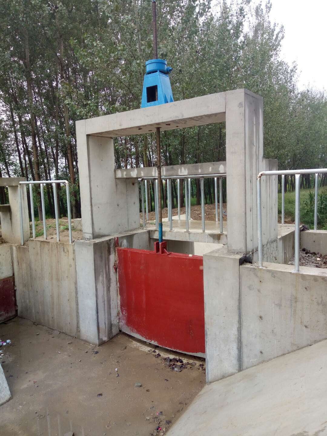 Cast iron gate mainly consists of frame, gate plate, metal sealing surface with tin bronze and adjustable wedge-shaped pressing block. The gate has the characteristics of strong structure, strong wear resistance and corrosion resistance, easy installation and use. When the sealing surface of the gate is worn out for a long time, the position of the wedge can be adjusted, and the original sealing performance can be restored. A. It is generally required that the safety factor of the tensile strength of gate components should not be less than 5 under large working head. The corrosion allowance of 2 mm is increased on the basis of calculation. B. The gate frame is square to match the groove section. When the gate is in full open position, at least half of the gate is still contained in the gate frame. The lower edge of the brake frame shall be machined with a concave groove, in which a copper sealing seating surface is embedded, and a countersunk screw made of the same material as the sealing seating surface shall be connected to the brake frame. The sealing seating surface shall be machined to a surface roughness of less than 3.2 um. The back of the brake frame should also be machined so that it can be directly bolted to the machined surface of the embedded wall frame. The joint of gate frame and wall frame should be filled with adhesive during installation. C. The gate, guide rail and lifting lug gate are integrally cast, rectangular, with integrally cast horizontal and vertical reinforcing bars. In case of heavy load, the deflection shall not be greater than 1/1500 of the length of the member. The sliding part of the gate shall have a processed concave groove. The groove shall be embedded with a copper sealing seating surface and connected with the gate with countersunk head screw made of the same material as the sealing seating surface. A step structure should be constructed at the sliding surface of each side of the whole gate length. The gap between the structure and the guide groove is less than or equal to 5mm. Wedges are arranged on all sides of the gate. The vertical central line above the gate plate should be consolidated or cast as a whole to connect the gate rod. The clearance between the side of the gate and the guide rail is not more than 3 mm. The guide rail is connected with the gate frame by stainless steel countersunk head screw or cast as a whole with the gate frame to prevent the relative movement between the guide rail and the gate frame. An adjustable top block is arranged at the bottom of the gate and the gate frame to prevent excessive wedging between the gate and the gate frame. The rod guide frame is equipped with rod guide frame to maintain the straightness of the rod, and has enough clearance for easy operation. The rod guide frame is made of gray cast iron with phosphorus bronze bushing and installed on the cast iron support. The distance between the guide frame and the support can be adjusted appropriately to meet the requirement of concentricity with the rod. After adjustment, the designed guide frame should be fixed on the shaft wall and keep its vertical line unchanged.


